I recently had the pleasure of commissioning a 3 acre (≈ 12,000 m2) rural land survey. The survey was delivered digitally as contour lines with a rad TRON-like stamp of George Washington:

Given that I own a small CNC mill (purchased when I got carried away building my artistial cell phone last year), the obvious next step was to build a coffee table scale model.
This article overviews that project:
- I bet everyone does this, it’ll be easy! (Frustrated attempts w/ off-the-shelf tools)
- Wait, I haz programmer! (Computational geometry in Clojure)
- Cool, Visual Basic Macros! (Scripting CAD software)
- I wish I had a table saw. (Buying wood + CNC milling)
Frustrated attempts
The survey was delivered as a DXF file of 1’ contour lines. All of the contours are open lines, since my land doesn’t have any peaks or valleys:
To actually create a physical model, these open contour lines need to converted into a closed 3D model that I can import into Autodesk’s Inventor CAD software (which I use for all of my modeling and CNC milling).
I first tried simply importing the contour lines into Inventor, which created them as “3D Sketch” objects. I tried the “loft” tool to connect each contour to the next, but the results looked wonky:
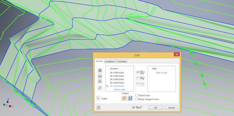
Worse, I couldn’t find a way to loft all of the lines together at once — and with 250 contour lines containing 30,000-ish vertexes, there’s no way I’m clicking each line segment manually.
Next I tried creating a solid in Sketchup: There’s a promising menu item Draw -> Sandbox -> From Contours which creates a TIN (triangulated irregular network) surface:
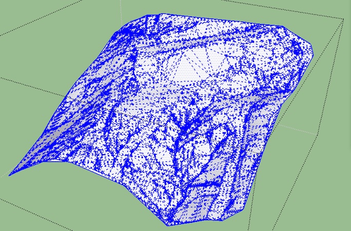
I tried using this surface to cut a solid cube in two (the bottom would be the desired land model) but I couldn’t figure out how to do it in either Sketchup or in Inventor (via DXF export from Sketchup). Inventor also got very slow and cranky when manipulating the TIN surface, which didn’t bode well for its willingness to use the surface in a boolean operation.
When I started, I assumed this would be an easy project: Surely turning contour data into a 3D solid is a common task and there’d be a great writeup about how to do it! Nope! At least, not that I could find — I now suspect that 99% of contour models are made by interns with an x-acto knife, glue stick, and chipboard.
Unfortunately, I don’t have any interns. However, I remembered that I can program computers to do my drudge work.
Computational Geometry
My overall strategy was to program Inventor to do whan an intern would: Build up the model from the bottom up using thin slices. My algorithm was, at each level, to:
- extend the contour line(s) to the 2D boundary containing all contour lines
- create the appropriate polygon(s) from the contour line(s) and boundary
- extrude the polygon(s) up to the next contour level (in my case, 1’), and merge the resulting solid with the levels below
Before I could start this algorithm, I needed to get the contour data into my programming language of choice, Clojure. The delivered data format, AutoCAD DXF, dates back to 1982 and shows it:
100
AcDbEntity
8
0
100
AcDb2dPolyline
70
1
30
12948.0
0
VERTEX
10
55903.6796875
20
44263.17578125
I tried using a Java library, kabejka, but couldn’t get that working. After skimming the 270 page spec, I couldn’t bring myself to write a DXF parser either.
Instead, I used Sketchup to export a KMZ file, which is a zip file containing a DAE file, which is some kind of XML. Scrolling through this XML I found some nodes that looked like the contour lines I want:
<geometry id="ID135">
  <mesh>
    <source id="ID136">
      <float_array id="ID138" count="57">56026.0127640 44328.8423760 13044.0000000 56027.3280960 44338.3744920 13044.0000000 56020.4471640 44365.4652480 13044.0000000 56020.0800000 44366.6400000 13044.0000000 56010.7807680 44395.2984360 13044.0000000 56001.2146440 44423.8692240 13044.0000000 55991.4774480 44452.3839000 13044.0000000 55981.6649760 44480.8740000 13044.0000000 55971.8730480 44509.3710600 13044.0000000 55962.1974720 44537.9066280 13044.0000000 55960.9200000 44541.7200000 13044.0000000 55952.1300960 44568.7152360 13044.0000000 55943.5594320 44595.7866720 13044.0000000 55934.8972800 44622.8252520 13044.0000000 55925.8329240 44649.7219200 13044.0000000 55918.8000000 44669.1600000 13044.0000000 55909.7881560 44690.4779280 13044.0000000 55899.7832520 44711.3831040 13044.0000000 55891.8000000 44728.2000000 13044.0000000</float_array>
      <technique_common>
        <accessor count="19" source="#ID138" stride="3">
          <param name="X" type="float" />
          <param name="Y" type="float" />
          <param name="Z" type="float" />
        </accessor>
      </technique_common>
    </source>
    <vertices id="ID137">
      <input semantic="POSITION" source="#ID136" />
    </vertices>
    <lines count="18" material="Material2">
      <input offset="0" semantic="VERTEX" source="#ID137" />
      <p>0 1 1 2 2 3 3 4 4 5 5 6 6 7 7 8 8 9 9 10 10 11 11 12 12 13 13 14 14 15 15 16 16 17 17 18</p>
    </lines>
  </mesh>
</geometry>
I used Christophe Grand’s Enlive (aliased as e) to extract these nodes and convert them into maps (one map per curve, containing the :z (height) and the ordered list of the curve’s :points):
(def contours
  (->> (for [f (e/select (e/html-resource (java.io.File. "contours.dae"))
                         ;;ignore the two closed contours in this dataset
                         [[:float_array (e/but :#ID714) (e/but :#ID11)]])]
         (let [points (-> (:content f)
                          first
                          (str/split #"\s")
                          (->> (map #(Float/parseFloat %))
                               (partition 3)))]
           {:z (-> points first last)
            :points (mapv (fn [[x y _]] [x y]) points)}))
       ;;remove contours shorter than 1 ft
       (remove (fn [c]
                 (> 12 (.getLength (line (:points c))))))
       (sort-by :z)))
(I’m leaving out plenty of details, so check out the full code listing at the end of this article for the gnarly details.)
With the data now in familiar turf (i.e., Clojure), I started to implement my algorithm. While developing each step, I used two techniques to make sure I didn’t mess anything up.
First, I continually exported pieces of work-in-progress geometry out as DXF so I could view it in Sketchup. This allowed me to visually check that everything was working — that lines weren’t flying off to infinity, intersecting with each other, &c.
Second, I checked some invariant properties of contours. For example, since this tract of land has no vertical cliffs or overhangs, contours should never intersect:
(let [lines (map #(line (:points %)) contours)]
  (->> (for [l lines
             l' lines]
         (when (and (not= l l')
                    (.intersects l l'))
           [l l']))
       (remove nil?)))
The first step of my algorithm is to extend the ends of each contour out to the closest side of the bounding box. This step is relatively straightforward: Assume the first and last points of the line are the endpoints, then find the corresponding point on the closest boundary edge:
(defn boundary-point
  [point]
  (let [[x y] point]
    (case (closest-edge point)
      :north [x (:y-max bb)]
      :south [x (:y-min bb)]
      :east  [(:x-max bb) y]
      :west [(:x-min bb) y])))
The second step, choosing which polygons to keep (i.e., which ones are land, and which ones are air), is more difficult. In particular, it’s tricky when there are multiple contours at the same level (which happens when, for example, there are separate hills on opposite sides of the property):
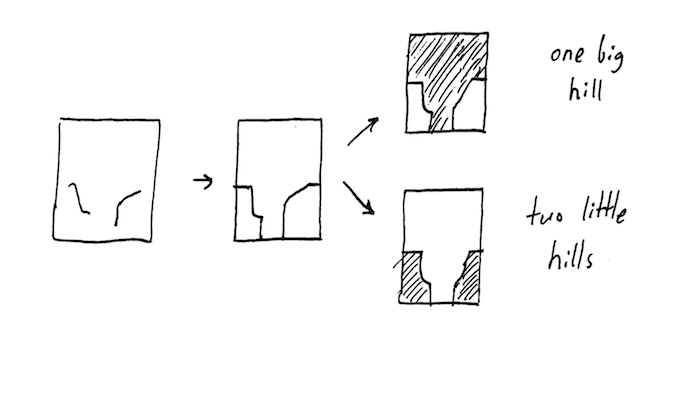
The algorithm I wrote looked at the polygons on each level and only kept those polygons that were fully supported by the polygons directly beneath them. At the bottom, I just chose the largest polygon.
Here’s that algorithm in Clojure; level-polygons is a set of all possible polygons derived from the contour lines and boundary of that level:
(defn close-contours
  [contours]
  (->> (group-by :z contours)
       sort
       (reduce (fn [levels-below level]
                 (let [polygons (if (empty? levels-below)
                                  ;;we're at the bottom, so just pick the largest possible polygon and hope that works.
                                  (->> (level-polygons level)
                                       (sort-by #(.getArea %))
                                       last
                                       vector)

                                  ;;otherwise, choose the polygons that're fully supported by polygons directly below 'em
                                  (let [directly-underneath (:polygons (last levels-below))]
                                    (->> (level-polygons level)
                                         (filter (fn [p]
                                                   (some #(.covers % p) directly-underneath))))))]
                   (conj levels-below {:z (first level) :polygons polygons})))
               [])))
Exporting the results back into Sketchup for visual inspection confirmed that this approach worked:
Note that visually it’s obvious that there’s a missing level; this is confirmed by analyzing the raw contour data:
(->> contours
       (map :z)
       distinct
       sort
       (partition 2 1)
       (map (partial apply -))
       distinct)
;;=> (-12.0, -24.0)
so I’ll have to have a harsh word next time I see the surveyor = )
Regardless, I now have 185 closed polygons that need to be cut out of virtual chipboard and virtual stick-glued together to make a solid 3D model.
Building a model in Inventor / CAM
All my Clojure program has given me is a set of polygons, which I need to get into the Inventor modeling software somehow. I’m definitely not going to draw them up manually one sketch at a time — luckily Inventor has an inviting “VBA Editor” button:
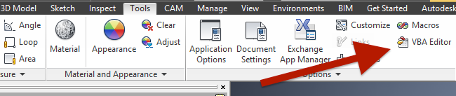
that pops up a lil’ Visual Basic IDE. After some quality time with the built-in Inventor API docs and Mod the Machine (a blog about scripting Inventor), I managed to create a new sketch and extrude it into a cube:
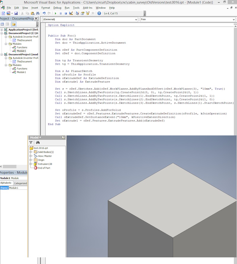
So now all I needed to do is export my closed contours into some kind of CSV, figure out how to read that via Visual Basic, and loop over the points to create and extrude the sketches.
Just kidding! I used Clojure to string concatenate together a 6,000ish line Visual Basic program that I just copy/pasted into Inventor. But that’s when disaster struck:
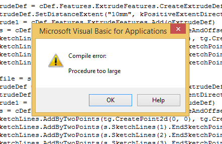
Apparently Visual Basic (first released in 1991) has a 64kB procedure size limit.
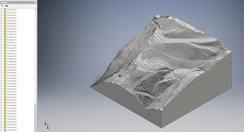
Determined not to learn Visual Basic, I installed Visual Studio 2016 and used Clojure to generate a 6,000ish line C# program that talked to Inventor over COM.
This program ran much more slowly than the Visual Basic program until I discovered that disabiling the Inventor UI during my script (via app.ScreenUpdating = false;) gave me a 6x speedup.
In the end, it worked out great:
Buying wood + milling
My Shopbot Desktop CNC mill has a working area of 18" × 24" × 5.5", and since the land is roughly square I decided on a 16" × 16" first model (4/1000 scale). Each contour step is then 0.004 × 1’ = 3/64" ≈ 1.2 mm high.
If I were using an x-acto knife or laser cutter to make this model, I’d need to pick up 1.2mm thick chipboard, then cut, align, and glue each contour. However, since I’m using a CNC machine that can make controlled-depth cuts (unlike a laser cutter, which cuts completely through material), it’s easier to start from a solid and remove the parts that aren’t part of the final model.
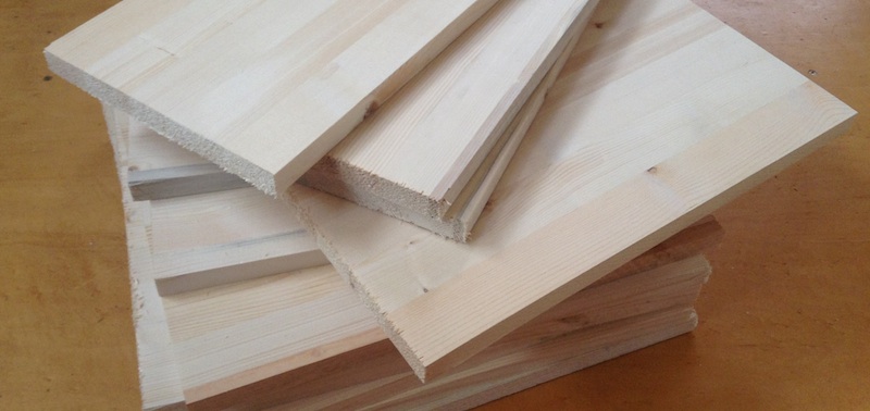
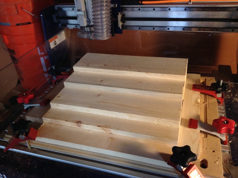
Bamboo and walnut both mill very well, but to keep costs down on the initial model I picked up cheap wood from Lowe’s: This ¾" laminated pine board cost $11 in 16" × 48" sheets (which they helpfully cut down into three 16" squares per sheet):
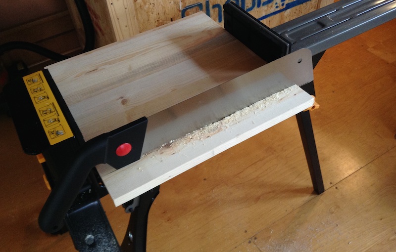
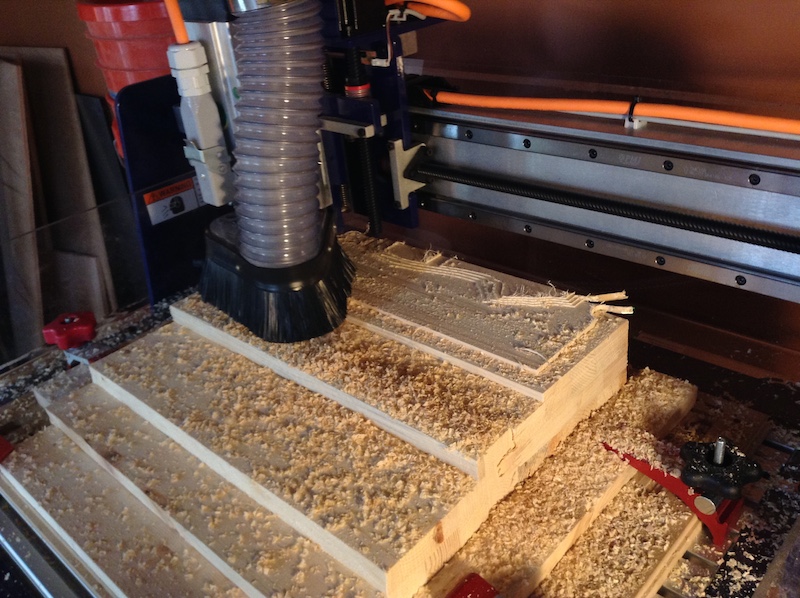
To reduce the milling time, I did a manual “roughing pass”, removing excess stock from parts of the model that I knew would be air. Since I don’t have a table saw, I had to do it the old-fashioned way:
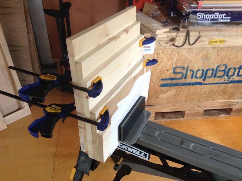
I then glued these sheets together to make the final stock:
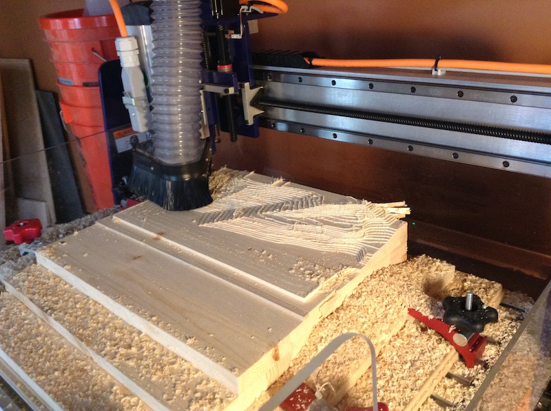
and generated the corresponding toolpath:
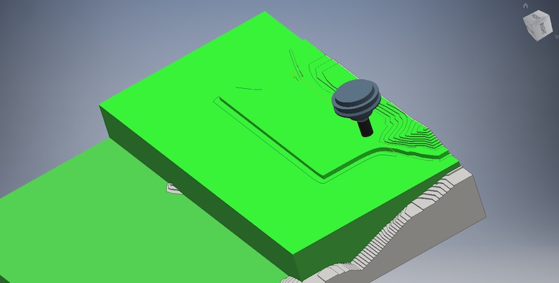
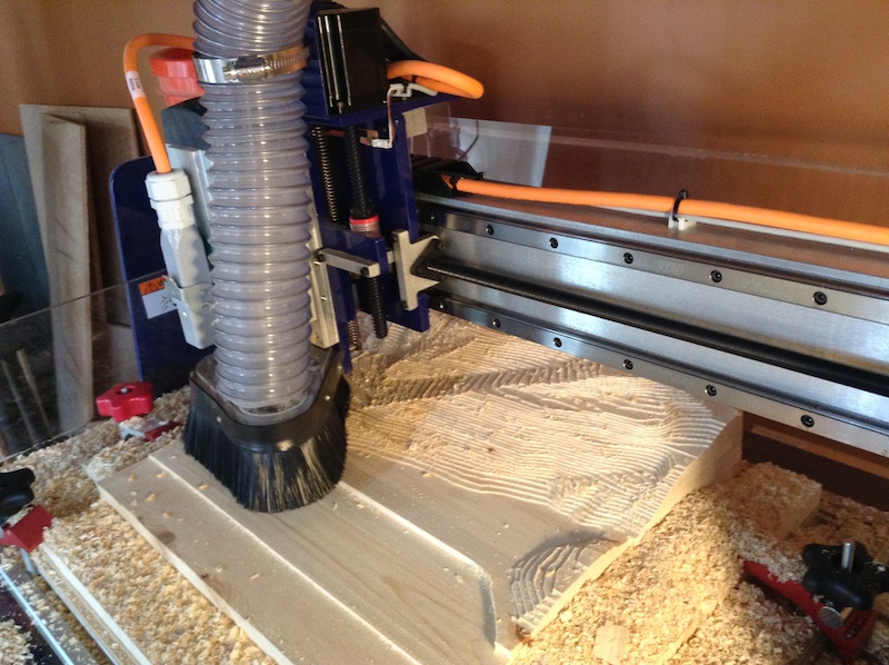
If you’re playing along at home: Onsurd 48-072 ½" two flute straight V bit at 9000 RPM with 6mm cut depth, 9mm material engagement, 108 inch/min feedrate. The machining time was about 90 minutes:
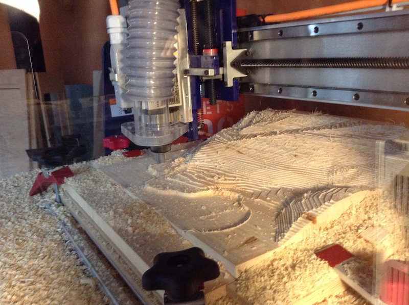
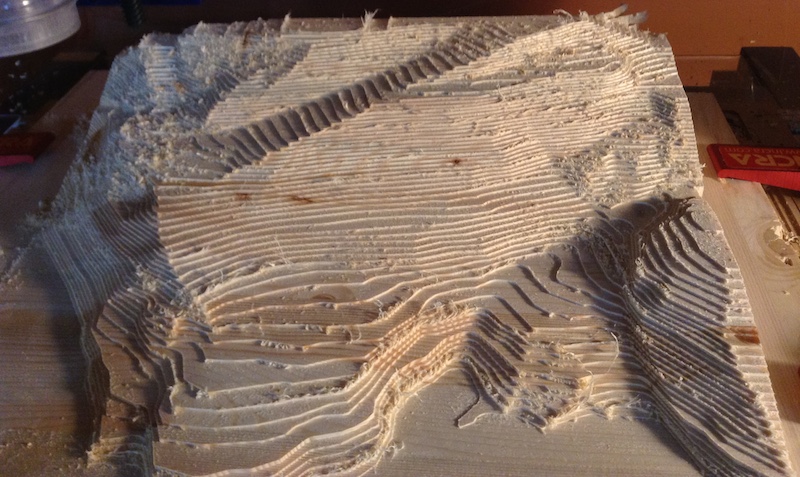
The final version turned out a bit fuzzy:
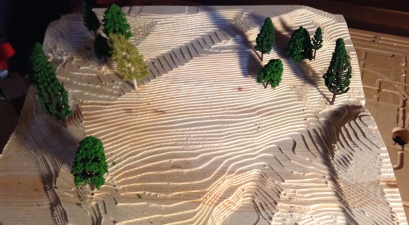
but 5 minutes of sanding and a $3 worth of fake plastic trees, fixed it right up:
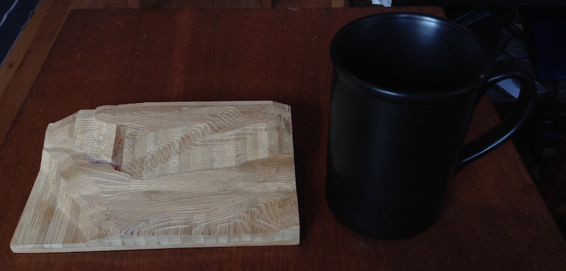
I also made an adorable coffee mug sized one out of bamboo scrap:
Thanks
Thanks to Zach Tellman for taking the time to chat about computational geometry. Thanks to Ryan Lucas for providing a nice garage home for my CNC mill.
Code appendix
I wrote this code to explore and (barely) solve my specific problem with a single dataset. It fails to handle edge cases, isn’t documented, and contains inappropriate comments. Several sections were written after I was a few whiskeys deep, so use at your own risk. = )
VBA Script to extrude a cube
Public Sub Foo()
    Dim doc As PartDocument
    Set doc = ThisApplication.ActiveDocument

    Dim cDef As PartComponentDefinition
    Set cDef = doc.ComponentDefinition

    Dim tg As TransientGeometry
    Set tg = ThisApplication.TransientGeometry

    Dim s As PlanarSketch
    Dim oProfile As Profile
    Dim oExtrudeDef As ExtrudeDefinition
    Dim oExtrude1 As ExtrudeFeature

    Set s = cDef.Sketches.Add(cDef.WorkPlanes.AddByPlaneAndOffset(cDef.WorkPlanes(3), "10mm", True))
    Call s.SketchLines.AddByTwoPoints(tg.CreatePoint2d(0, 0), tg.CreatePoint2d(0, 1))
    Call s.SketchLines.AddByTwoPoints(s.SketchLines(1).EndSketchPoint, tg.CreatePoint2d(1, 1))
    Call s.SketchLines.AddByTwoPoints(s.SketchLines(2).EndSketchPoint, tg.CreatePoint2d(1, 0))
    Call s.SketchLines.AddByTwoPoints(s.SketchLines(3).EndSketchPoint, s.SketchLines(1).StartSketchPoint)

    Set oProfile = s.Profiles.AddForSolid
    Set oExtrudeDef = cDef.Features.ExtrudeFeatures.CreateExtrudeDefinition(oProfile, kJoinOperation)
    Call oExtrudeDef.SetDistanceExtent("10mm", kPositiveExtentDirection)
    Set oExtrude1 = cDef.Features.ExtrudeFeatures.Add(oExtrudeDef)
End Sub
C# CLI program to make model
using System;
using System.Collections.Generic;
using System.Linq;
using System.Text;
using System.Threading.Tasks;
using Inventor;
using System.Diagnostics;

namespace ConsoleApplication1
{
    class Program
    {
        //http://stackoverflow.com/questions/12754761/why-could-com-interop-layer-be-40-times-slower-when-client-is-compiled-in-vs-201
        //Doesn't seem to help much for me
        [STAThread]
        static void Main(string[] args)
        {


            Inventor.Application app = (Inventor.Application)System.Runtime.InteropServices.Marshal.GetActiveObject("Inventor.Application");
            PartDocument doc = (PartDocument)app.ActiveDocument;
            TransientGeometry tg = app.TransientGeometry;
            Inventor.PartComponentDefinition c_def = doc.ComponentDefinition;

            app.UserInterfaceManager.UserInteractionDisabled = true;
            app.ScreenUpdating = false;

            PlanarSketch s;
            Profile profile;
            ExtrudeDefinition extrude_def;
            ExtrudeFeature extrude;

            Stopwatch watch = new Stopwatch();
            watch.Start();


            profile = s.Profiles.AddForSolid();
            extrude_def = c_def.Features.ExtrudeFeatures.CreateExtrudeDefinition(profile, Inventor.PartFeatureOperationEnum.kJoinOperation);
            extrude_def.SetDistanceExtent("0.048in", Inventor.PartFeatureExtentDirectionEnum.kPositiveExtentDirection);
            extrude = c_def.Features.ExtrudeFeatures.Add(extrude_def);
            s = c_def.Sketches.Add(c_def.WorkPlanes.AddByPlaneAndOffset(c_def.WorkPlanes[3], "51.936in", true));
            s.SketchLines.AddByTwoPoints(tg.CreatePoint2d(0.00000, 43.12821), tg.CreatePoint2d(45.26768, 43.12821));
            s.SketchLines.AddByTwoPoints(s.SketchLines[1].EndSketchPoint, tg.CreatePoint2d(45.26768, 0.00000));
            s.SketchLines.AddByTwoPoints(s.SketchLines[2].EndSketchPoint, tg.CreatePoint2d(1.76419, 0.00000));
            s.SketchLines.AddByTwoPoints(s.SketchLines[3].EndSketchPoint, tg.CreatePoint2d(1.75312, 0.97342));
            s.SketchLines.AddByTwoPoints(s.SketchLines[4].EndSketchPoint, tg.CreatePoint2d(1.16800, 2.72514));
            s.SketchLines.AddByTwoPoints(s.SketchLines[5].EndSketchPoint, tg.CreatePoint2d(0.00000, 2.72514));
            s.SketchLines.AddByTwoPoints(s.SketchLines[6].EndSketchPoint, s.SketchLines[1].StartSketchPoint);

            //6k lines of the same.

            app.UserInterfaceManager.UserInteractionDisabled = false;
            app.ScreenUpdating = true;
            System.Console.WriteLine(watch.Elapsed);

        }
    }
}
Clojure scratchpad for all geometry calculations
;;Add to yer project.clj deps:
;; [com.vividsolutions/jts "1.13"]
;; [enlive "1.1.6"]
;; [lonocloud/synthread "1.0.4"]


(ns scratch.contours
  (:require [net.cgrand.enlive-html :as e]
            [clojure.string :as str]
            [clojure.pprint :refer [pprint]]
            [lonocloud.synthread :as ->])
  (:import (com.vividsolutions.jts.geom
            GeometryFactory
            Coordinate
            Polygon
            LineString)
           com.vividsolutions.jts.operation.polygonize.Polygonizer
           com.vividsolutions.jts.simplify.TopologyPreservingSimplifier))


(def f
  (GeometryFactory.))

(defn ->coordinates
  [points]
  (into-array (for [[x y] points]
                (Coordinate. x y))))

(defn polygon
  [points]
  (.createPolygon f (.createLinearRing f (->coordinates points)) nil))

(defn line
  [points]
  (.createLineString f (->coordinates points)))

(defn point
  [p]
  (.createPoint f (first (->coordinates [p]))))


;;Load DWG into sketchup, remove stray trees and origin points, export as google earth KMZ, extract internal XML file (.dae)
;;must do this on MAC since the windows program orders the points off-by-one and fucks up my line closures

(def c
  (e/html-resource (java.io.File. "contours.dae")))

;;all tags in file
(comment
  (->> (tree-seq (constantly true) :content (first c))
       (map :tag)
       distinct)

  ;;There are 233 float array tags, and every one of them has a multiple of three number of floats --- looks like these could be our contour coordinates
  (->> (e/select c [:float_array])
       (map #(Integer/parseInt (get-in % [:attrs :count])))
       (every? #(= 0 (mod % 3)))))


(def contours
  ;;ignore the two closed contours in this dataset
  (->> (for [f (e/select c [[:float_array (e/but :#ID714) (e/but :#ID11)]])]
         (let [points (-> (:content f)
                          first
                          (str/split #"\s")
                          (->> (map #(Float/parseFloat %))
                               (partition 3)))]
           {:z (-> points first last)
            :points (mapv (fn [[x y _]] [x y]) points)}))
       ;;remove contours shorter than 1 ft
       (remove (fn [c]
                 (> 12 (.getLength (line (:points c))))))
       (sort-by :z)))


(def trees
  (->> (e/select c [:visual_scene :matrix])
       (map (fn [node]
              (let [xs (str/split (first (:content node)) #"\s")]
                (vec (for [i [3 7]]
                       (Float/parseFloat (xs i)))))))))


(defn bounds
  [xs]
  ((juxt (partial apply min) (partial apply max)) xs))


(let [points (mapcat :points contours)
      [x-min x-max] (bounds (map first points))
      [y-min y-max] (bounds (map second points))
      ;;stretch out bounding boxes by one foot to avoid roundoff topology errors near the edges
      offset 12]

  (def bb
    {:x-min (- x-min offset)
     :x-max (+ x-max offset)
     :y-min (- y-min offset)
     :y-max (+ y-max offset)}))

(def bb-area
  (* (- (:x-max bb) (:x-min bb))
     (- (:y-max bb) (:y-min bb))))

(def bb-corners
  [[(:x-min bb) (:y-min bb)]
   [(:x-min bb) (:y-max bb)]
   [(:x-max bb) (:y-max bb)]
   [(:x-max bb) (:y-min bb)]])

(def bb-line
  (->> bb-corners
       cycle
       (partition 2 1)
       (take 4)
       (apply concat)
       line))


(defn closest-edge
  [[x y]]
  (-> (sort [[(Math/abs (- x (:x-min bb))) :west]
             [(Math/abs (- x (:x-max bb))) :east]
             [(Math/abs (- y (:y-min bb))) :south]
             [(Math/abs (- y (:y-max bb))) :north]])
      first
      second))


(defn end-points
  [points]
  ((juxt first last) points))


(defn boundary-point
  [point]
  (let [[x y] point]
    (case (closest-edge point)
      :north [x (:y-max bb)]
      :south [x (:y-min bb)]
      :east  [(:x-max bb) y]
      :west [(:x-min bb) y])))


(defn level-polygons
  "All possible polygons made from this level's contours and the boundary."
  [[z cs]]
  (into  (.getPolygons (doto (Polygonizer.)
                            (.add (reduce (fn [res l]
                                            (.union res l))
                                          bb-line
                                          (for [{points :points} cs]
                                            ;;extend lines to boundary
                                            (line (concat [(boundary-point (first points))]
                                                          points
                                                          [(boundary-point (last points))])))))))))


(defn close-contours
  [contours]
  (->> (group-by :z contours)
       sort
       (reduce (fn [levels-below level]
                 (let [polygons (if (empty? levels-below)
                                  ;;we're at the bottom, so just pick the largest possible polygon and hope that works.
                                  (->> (level-polygons level)
                                       (sort-by #(.getArea %))
                                       last
                                       vector)

                                  ;;otherwise, choose the polygons that're fully supported by polygons directly below 'em
                                  (let [directly-underneath (:polygons (last levels-below))]
                                    (->> (level-polygons level)
                                         (filter (fn [p]
                                                   (some #(.covers % p) directly-underneath))))))]
                   (conj levels-below {:z (first level) :polygons polygons})))
               [])))


(defn point->dxf-vertex
  [[x y]]
  (str "0\nVERTEX\n10\n" x "\n20\n" y))

(defn contour->dxf-polyline
  ([c]
   (contour->dxf-polyline c 0))
  ([c height]
   (str "0\nPOLYLINE\n100\nAcDbEntity\n8\n0\n100\nAcDb2dPolyline\n70\n1\n30\n" height "\n"
        (->> (:points c)
             (map point->dxf-vertex)
             (str/join "\n"))
        "\n"
        "0\nSEQEND")))


(defn polygon->dxf-polyline
  ([p]
   (polygon->dxf-polyline p 0))
  ([p height]
   (contour->dxf-polyline {:points (for [c (.getCoordinates (.getExteriorRing p))]
                                     [(.-x c) (.-y c)])}
                          height)))


(defn dxf
  [entities]
  (str "999
HELLO WORLD
0
SECTION
2
ENTITIES\n"
       entities
       "\n0
ENDSEC
0
EOF"))


;;in Sketchup, map is about 370 ft x 350 ft, which is 3.0 acres, so it looks like the DXF isn't reduced in scale at all.

;;Imported data extent matches the sketchup measurement, so it looks like our raw units are inches
(/ (- (:x-max bb) (:x-min bb)) 12)
(/ (- (:y-max bb) (:y-min bb)) 12)

;;total height difference is 174 ft
(let [[low high] (->> contours
                      (map :z)
                      bounds)]

  (/ (- high low) 12))

;;shopbot cutting area is 24 x 18 x 3.5 inch
;;so scaling factor is: (/ 18.0 (* 12 350)) = .004

;;(* 0.004 (* 12 174)) = 8.4 inch model height

;;so we may need to do in 3, 3 inch sections

(def scale
  0.004)

(def cm-per-inch
  2.54)

(defn point->inventor
  [[x y]]
  ;;translate + scale so that the model lives at the origin in Inventor; turn our inches into inventor's base cm unit
  (->> [(* scale cm-per-inch (- x (:x-min bb)))
        (* scale cm-per-inch (- y (:y-min bb)))]
       (mapv #(format "%.5f" %))))


(defn inventor-slice
  [z polygon]
  (let [slice-height (str (* 12 scale) "in")
        z-height  (str (* z scale) "in")
        [a b & xs] (->> (.getCoordinates (.getExteriorRing polygon))
                        rest ;;first point is repeated, so we can throw it out.
                        (map (fn [c]
                               (point->inventor [(.-x c) (.-y c)]))))]
    (str

     ;;create sketch at appropriate height
     (str "s = c_def.Sketches.Add(c_def.WorkPlanes.AddByPlaneAndOffset(c_def.WorkPlanes[3], \"" z-height"\", true));\n")

     ;;first polygon line
     (str "s.SketchLines.AddByTwoPoints("
          "tg.CreatePoint2d(" (first a) "," (second a) ")"
          ", "
          "tg.CreatePoint2d(" (first b) "," (second b) ")"
          ");\n")

     ;;inner polygon lines
     (->> xs
          (map-indexed (fn [idx p]
                         (str "s.SketchLines.AddByTwoPoints(s.SketchLines[" (inc idx) "].EndSketchPoint, tg.CreatePoint2d(" (first p) "," (second p) "));")))
          (str/join "\n"))

     "\n"
     ;;last line connects end point back to starting point
     (str "s.SketchLines.AddByTwoPoints(s.SketchLines[" (inc (count xs)) "].EndSketchPoint, s.SketchLines[1].StartSketchPoint);\n")


     ;;extrusion
     "
profile = s.Profiles.AddForSolid();
extrude_def = c_def.Features.ExtrudeFeatures.CreateExtrudeDefinition(profile, Inventor.PartFeatureOperationEnum.kJoinOperation);
extrude_def.SetDistanceExtent(\"" slice-height "\", Inventor.PartFeatureExtentDirectionEnum.kPositiveExtentDirection);
extrude = c_def.Features.ExtrudeFeatures.Add(extrude_def);\n"
)))


(comment

  (->> contours
       (map :z)
       distinct
       sort
       (partition 2 1)
       (map (partial apply -))
       pprint)


  (->> contours
       (map :points)
       (map count)
       sort)

  (->> contours
       (map #(.getLength (line (:points %))))
       sort)


  (->> (close-contours contours)
       (mapcat (fn [{:keys [z polygons]}]
                 (for [p polygons]
                   (polygon->dxf-polyline p z))))
       (str/join "\n")
       dxf
       (spit "/media/sf_Dropbox/foo.dxf"))


  (->> (close-contours contours)
       (map (fn [{:keys [z polygons]}]
              (prn z)
              (for [p (->> polygons
                           (map identity))]
                (count (.getCoordinates p)))))
       (take 10))


  ;;34 s to do trees + 20 layers w/ UI; 6 seconds without UI


  ;; 7:41 to do all layers at 6 inch simplification
  (->> (close-contours contours)
       (map (fn [{:keys [z polygons]}]
              (for [p (->> polygons
                           (map #(TopologyPreservingSimplifier/simplify % 6.0)))]
                (inventor-slice z p))))

       flatten
       str/join

       ;;add trees layer
       (str "s = c_def.Sketches.Add(c_def.WorkPlanes[3]);\ns.Name = \"trees\";\n"
            (->> (for [[x y] (->> trees
                                  (map point->inventor))]
                   (str "s.SketchPoints.Add(tg.CreatePoint2d(" x "," y "));\n"))
                 str/join))
       print)


  ;;Do any contour lines intersect? they shouldn't!
  (let [lines (map #(line (:points %)) contours)]
    (->> (for [l lines
               l' lines]
           (when (and (not= l l')
                      (.intersects l l'))
             [l l']))
         (remove nil?)))


  ;;Lets check that points->polygon consistently divides the bounding box into two disjoint pieces
  (->> contours
       (map #(let [[a b] (seq (points->polygons (:points %)))]
               (+ (.getArea a) (.getArea b))))
       frequencies)


  (->> (close-contours contours)
       (mapcat :polygons)
       ;;32850 raw points
       (map #(TopologyPreservingSimplifier/simplify % 12.0))
       (map #(.getNumPoints %))
       (reduce +))


  )